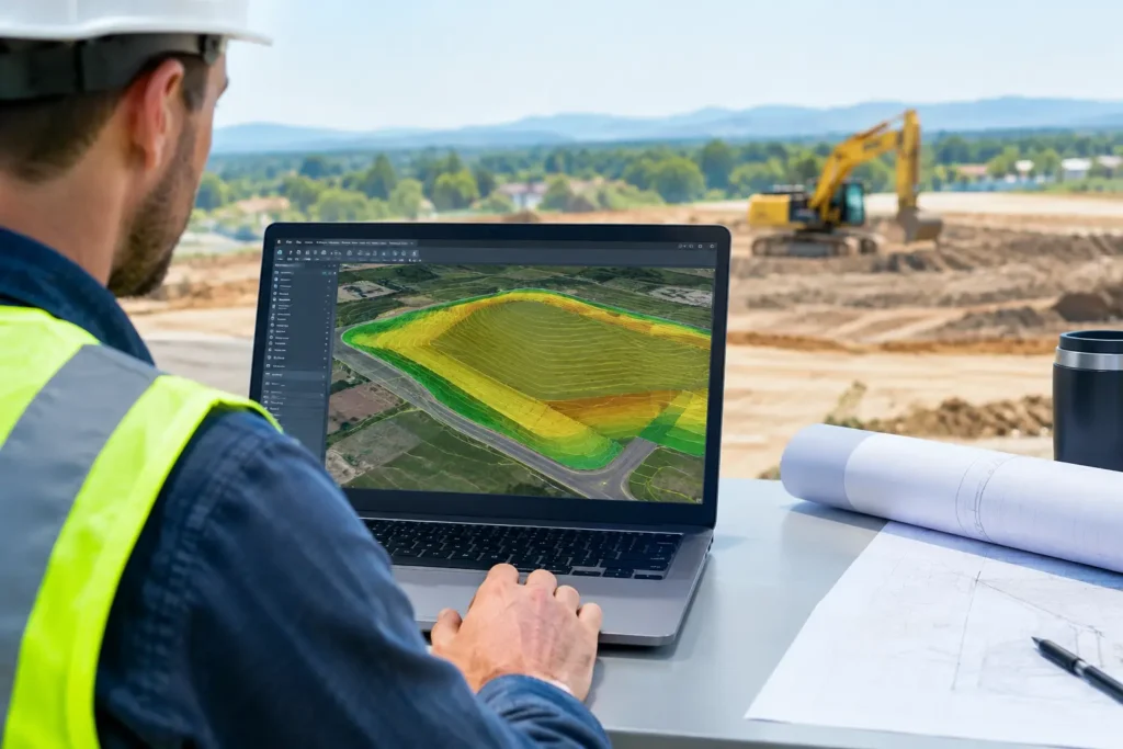
A site plan can look complete on paper while still failing in the field. A driveway may not drain, a retaining wall may exceed a practical height, or an access road may clash with an existing utility corridor. Civil 3D grading turns proposed levels, slopes, and drainage intent into an intelligent 3D model that can be checked before construction begins. For civil engineers, infrastructure designers, and site-development professionals, this is a capability that directly affects design quality, quantities, coordination, and project confidence.
What Civil 3D Grading Actually Solves
Grading is the controlled shaping of land to meet design requirements. It connects existing terrain to finished pads, roads, parking areas, swales, channels, sidewalks, retaining structures, and drainage systems. In Civil 3D, the process is not limited to drawing contour lines or assigning spot elevations. It uses dynamic relationships between surfaces, feature lines, grading criteria, corridors, alignments, profiles, and labels.
The practical value is clear. When a finished floor elevation changes, a properly structured model can update dependent slopes and surfaces. When a road profile is revised, the corridor and earthwork results can be reviewed again. This does not eliminate engineering judgment, but it reduces the risk of relying on disconnected drawings and manual calculations.
For projects across Dubai and the GCC, grading is especially relevant where fast-track construction, mixed-use developments, industrial sites, roadworks, and large external works packages demand reliable coordination. A well-built Civil 3D model gives design teams a clearer basis for discussion with surveyors, drainage engineers, utilities teams, BIM coordinators, contractors, and clients.
The Core Elements of Civil 3D Grading
A successful workflow begins with the existing ground surface. Survey points, breaklines, contours, and boundary data are organized to create an Existing Ground, or EG, surface. This surface must be reviewed carefully. Incorrect point codes, missing breaklines, or poor boundaries can produce misleading contours and unreliable volume calculations.
The next stage is defining design control. Designers commonly use feature lines because they carry both geometry and elevation. A feature line may represent the edge of pavement, top of curb, toe of slope, pad edge, channel invert, or top and bottom of a retaining wall. Unlike simple 2D polylines, feature lines can be edited by elevation, assigned relative grades, and used to build proposed surfaces.
Grading criteria then apply engineering rules to the model. A criterion may create a slope at a specified ratio, grade to a target elevation, daylight to an existing surface, or follow a set distance. For example, a building pad may grade outward at 2 percent for drainage before daylighting at a 3:1 slope to existing ground. The correct choice depends on geotechnical requirements, site constraints, local authority standards, accessibility needs, drainage strategy, and constructability.
A proposed Finished Ground, or FG, surface brings these design elements together. Once it is built, the team can inspect contours, analyze slopes, identify low points, calculate cut and fill, and produce sections. That is where a grading model becomes a decision-making tool rather than a drafting exercise.
Why Feature Lines Matter So Much
Many beginners focus on commands before understanding control geometry. Feature lines are often the difference between a model that is easy to revise and one that becomes difficult after the first design change. They establish where elevation must be controlled and how the ground should transition between important edges.
A parking area, for instance, needs more than a flat surface. It requires deliberate fall toward inlets, suitable crossfall for vehicle movement, transitions at curbs, and coordination with adjacent building entrances. Feature lines allow the designer to model these conditions with intent. The surface then interpolates between the controls.
This approach also makes quality checks more meaningful. Rather than asking whether contours look smooth, the engineer can confirm whether critical levels, slopes, and drainage paths are correct.
A Practical Civil 3D Grading Workflow
Professional grading work benefits from a disciplined sequence. Start by reviewing survey data, coordinate systems, units, drawing scale, and existing surface quality. Establish a clean template with styles for surfaces, feature lines, grading objects, labels, and volume reports. Consistent standards save significant time when multiple team members contribute to the same project.
Then define the grading strategy before modeling every line. Identify fixed levels such as road tie-ins, finished floor levels, utility crossings, entrance thresholds, drainage outfalls, and boundary constraints. These controls often determine the feasible grading solution long before detailed contours are generated.
Create feature lines for pads, pavement edges, channels, and retaining conditions. Apply elevations deliberately through absolute levels, relative elevation commands, or grade-between-points tools. Build grading objects where daylight slopes or controlled transitions are required, then add breaklines to the FG surface. Finally, use surface analysis to review elevation bands, slope arrows, watershed behavior, and contour patterns.
Volumes should be checked at more than one stage. Early estimates guide feasibility, while later calculations support tender quantities and construction planning. A balanced cut-and-fill result may be desirable, but it is not automatically the best outcome. Imported fill quality, unsuitable excavated material, disposal costs, compaction requirements, hauling distance, and staging constraints all influence the final earthwork decision.
Common Modeling Mistakes to Avoid
The most costly errors are usually not command errors. They are workflow errors. Building a proposed surface from uncontrolled contours, using too few breaklines, or changing feature line elevations without checking downstream effects can distort the site model.
Another common issue is treating drainage as an afterthought. A surface may look visually acceptable while holding water against a building, creating disconnected flow paths, or failing to reach a defined outfall. Designers should inspect low points, confirm positive drainage, and coordinate inlets, pipes, channels, and structures as the grading develops.
It is also essential to separate design surfaces clearly. Existing ground, demolition surfaces, subgrade surfaces, and finished ground surfaces may all be needed on complex projects. Clear naming and data management prevent quantity errors and make model handover far more reliable.
Civil 3D Grading for Roads, Plots, and Infrastructure
Civil 3D grading is used differently depending on the project type. For a residential or commercial plot, the primary focus may be finished floor levels, parking grades, access ramps, boundary tie-ins, and stormwater direction. For an industrial development, large pads, truck circulation, warehouse thresholds, service yards, and material quantities may drive the design.
Road and infrastructure projects add another layer of coordination. Alignments, profiles, assemblies, subassemblies, and corridors establish the road geometry, while grading resolves tie-ins to adjacent land, side slopes, medians, intersections, channels, and access roads. Corridor surfaces can support detailed earthwork evaluation, but they still require engineering review at transitions and constrained locations.
The strongest designers know when to use grading objects and when to use feature lines, corridors, or a combination of methods. A corridor can efficiently model a long roadway, while a feature-line-based approach may be more flexible around a small parking area or irregular building pad. The correct method depends on design intent, project scale, revision frequency, and required deliverables.
Training That Builds Project-Ready Capability
Learning Civil 3D grading is most valuable when it is taught through real site conditions rather than isolated commands. Engineers and students should practice creating existing and proposed surfaces, setting feature line elevations, grading pads to daylight, modeling parking lots, calculating volumes, producing surface labels, and identifying drainage issues from actual design scenarios.
At CADD International, Civil 3D programs can be structured for beginners, working civil engineers, infrastructure teams, and corporate groups. Training can include online, offline, or hybrid sessions for professionals in Dubai, Sharjah, Abu Dhabi, Ajman, Ras Al Khaimah, and across the UAE. Learners can also choose one-on-one, premium private, customized, advanced-topic, and project-assistance sessions based on their experience and project requirements.
For online participants from Oman, Saudi Arabia, Kuwait, Bahrain, Qatar, Egypt, Sudan, and other MENA locations, sessions can cover site grading fundamentals, road corridor grading, earthwork quantity workflows, drainage-aware surface design, and drawing production. Delivery in English, Arabic, Hindi, Malayalam, Tamil, or Kannada helps teams focus on technical application without losing clarity. Corporate training can be arranged around company standards, live project challenges, and licensed software environments.
Placement support and practical project exposure also matter for professionals building their next career move. Employers do not only look for software certificates. They look for engineers and designers who can interpret levels, understand site constraints, organize a model, detect grading risks, and communicate design intent clearly.
Build Confidence Before the Ground Is Moved
Civil 3D grading is where terrain, design intent, and construction reality meet. The software can generate surfaces and quantities quickly, but the real professional advantage comes from knowing what to control, what to check, and when a result needs engineering reconsideration. Build that judgment through guided practice, realistic project models, and a workflow that treats every elevation as a construction decision.