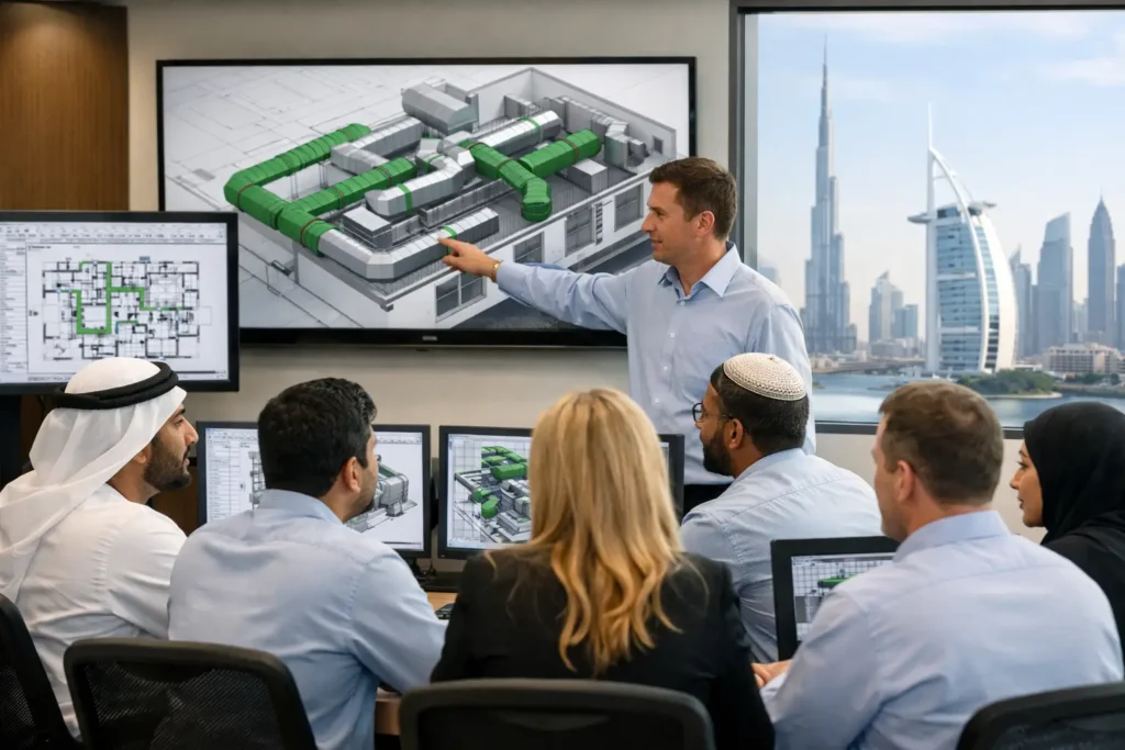
A duct route that looks clean in plan view can still fail on site. It may pass through a structural beam, block an access panel, exceed a ceiling void, or leave no room for insulation and maintenance. Revit duct modeling gives HVAC and MEP professionals a practical way to identify these issues before fabrication, installation, and costly coordination meetings begin.
For engineers and designers working toward opportunities in the UAE and GCC construction market, duct modeling is more than a software command. It is a BIM discipline that connects HVAC design intent, building geometry, equipment selection, clearances, documentation, and multidisciplinary coordination. A well-built model can support faster decisions from the design stage through construction.
Why Revit Duct Modeling Matters on Real MEP Projects
HVAC systems compete for limited ceiling and service-space volume. Ductwork often shares the same corridor with chilled-water pipes, fire protection mains, cable trays, electrical containment, plumbing lines, and structural elements. When each discipline works only from separate 2D drawings, conflicts can remain hidden until the installation team reaches the site.
Revit creates a coordinated 3D environment where duct systems are modeled as intelligent building elements. Ducts can carry dimensions, elevations, system classifications, materials, insulation data, and flow-related information. This allows a designer to see not only where a duct runs, but also what system it belongs to and whether its route is realistic within the available space.
The value is especially clear on hospitals, high-rise towers, malls, airports, industrial facilities, and large residential developments. These projects contain dense MEP zones where a minor routing change can affect shafts, false ceilings, diffuser locations, quantities, and installation sequencing. Employers increasingly expect junior engineers and experienced HVAC professionals to understand this BIM-based workflow.
The Core Skills Behind Accurate Duct Models
Effective duct modeling starts before the first duct segment is drawn. The model must have the correct architectural and structural backgrounds, levels, grids, linked files, and shared coordinates where required. Without this foundation, a technically correct HVAC layout can still be misaligned with the building model.
Setting up HVAC systems and equipment
A modeler first places or coordinates the mechanical equipment that drives the system, such as air handling units, fan coil units, exhaust fans, fresh-air units, and variable air volume boxes. Connectors, system types, and equipment parameters matter because they establish how ducts are generated and connected.
Supply air, return air, exhaust air, fresh air, and smoke extraction systems should be clearly classified. Clear system naming helps the entire project team read the model and makes views, schedules, filters, and coordination reviews easier to manage. It also reduces the risk of connecting a duct to the wrong service during busy design revisions.
Routing ducts with practical site awareness
Revit can create duct runs automatically between components, but automatic routing is only a starting point. The modeler must assess duct size, shape, elevation, slope where applicable, fitting selection, and clearance from other services. A route that is mathematically connected is not always installable.
Rectangular ducts may suit congested ceiling zones, while round ducts can be more efficient in certain applications. The right selection depends on airflow requirements, pressure loss, available space, architectural intent, fabrication standards, and project specifications. Modeling professionals need to understand these trade-offs rather than treating every duct run as a simple visual exercise.
Fittings require equal attention. Elbows, transitions, tees, offsets, dampers, flexible connections, and access requirements all affect coordination. A strong model includes sensible routing decisions and avoids unnecessary bends that may complicate fabrication or reduce system performance.
Connecting terminals and maintaining design intent
Air terminals are the visible end of many HVAC systems, but their location is shaped by room use, reflected ceiling plans, lighting layouts, interior finishes, and air distribution requirements. Revit helps designers connect diffusers, grilles, and registers back to their duct systems while reviewing their placement in coordinated ceiling views.
This is where communication between disciplines becomes essential. An interior ceiling pattern may need adjustment to maintain diffuser alignment. A lighting fixture may need to move. A duct elevation may need to change. BIM coordination is not about proving one discipline right. It is about resolving conflicts early enough to protect the project schedule and quality.
From Model Geometry to BIM Coordination
A duct model becomes far more valuable when it is checked as part of a coordinated BIM process. Revit views, section boxes, filters, and worksets can help teams isolate systems and inspect congested areas. Engineers can review risers, plant rooms, service corridors, shafts, and ceiling voids in 3D rather than relying on assumptions from plan drawings.
For formal clash detection, duct models are often reviewed with structural, architectural, electrical, plumbing, and fire protection models in coordination software such as Navisworks Manage. The goal is not to eliminate every intersection automatically. Some clashes are intentional or acceptable, while others are critical. A duct passing through a designated opening may be valid; a duct colliding with a deep transfer beam is not.
The modeler must therefore learn how to classify clashes, investigate the reason behind them, propose alternatives, and communicate changes clearly. This practical judgment is what separates a software operator from a BIM-ready MEP professional.
Documentation is another major outcome. When the model is organized properly, Revit can generate duct plans, sections, elevations, schedules, and quantity information. However, automated output still requires engineering review. Incorrect parameters, unconnected systems, inconsistent naming, or incomplete family data can produce misleading schedules. Quality control remains a professional responsibility.
A Career-Focused Learning Path for HVAC Professionals
Beginners often make the mistake of learning Revit commands without understanding HVAC workflows. They can draw ducts, but struggle to develop an organized system, coordinate a riser, read a mechanical drawing, or respond to a site-driven revision. The best learning path combines software practice with project logic.
A focused Revit MEP program should cover interface navigation and project setup, linked architectural and structural models, mechanical settings, equipment placement, duct routing, air terminals, fittings, annotations, schedules, sheets, and coordination review. As confidence grows, learners should work on project-style exercises such as office floors, residential buildings, commercial spaces, or mechanical rooms.
Live-project assistance is particularly useful for professionals who already work in contracting, design consultancy, facilities, or construction coordination. It helps them translate real drawing issues into better modeling decisions. One-on-one, premium private, and customized sessions can also address advanced requirements such as complex duct risers, plant room layouts, BIM execution workflows, model audits, and clash-resolution support.
CADD International Sharjah provides career-focused BIM learning for students and working professionals seeking practical Revit and HVAC coordination skills aligned with industry expectations. Training can be structured for individuals or corporate teams, with instructor-led online and offline options, valid-license environments, and project-oriented guidance.
Online Revit Duct Modeling Sessions Across MENA
Online training can be highly effective when it includes live instructor interaction, screen-based demonstrations, guided exercises, model reviews, and structured assignments. It is especially suitable for professionals who need to upgrade skills without pausing work commitments or relocating.
For learners in Oman, sessions can focus on HVAC system setup, duct routing, equipment connections, and coordinated documentation for commercial and residential projects. Professionals in Saudi Arabia may benefit from advanced coordination exercises for large-scale towers, hospitality, industrial, and infrastructure-related developments, where service congestion and BIM standards are often demanding.
Participants from Kuwait, Bahrain, Qatar, Egypt, and Sudan can join online programs designed around mechanical modeling fundamentals, ceiling coordination, duct schedules, clash review, and drawing production. The course pace can be adapted for fresh engineering graduates, MEP draftsmen transitioning from AutoCAD, site engineers, and experienced HVAC professionals moving into BIM coordination roles.
Sessions can be delivered in English, Malayalam, Hindi, Tamil, Kannada, and Arabic, helping learners focus on technical understanding without unnecessary language barriers. International learners may also choose private sessions, advanced-topic sessions, customized corporate batches, and project assistance based on their role and project requirements.
Building a Model That Employers Can Trust
The strongest Revit models are not necessarily the most visually complex. They are organized, coordinated, readable, and useful to the people who need them. A hiring manager or project lead will recognize the difference when a candidate can explain why a duct elevation changed, how a clash was resolved, or how a schedule was checked before issue.
Treat every duct route as a construction decision, not just a line on a screen. That mindset will make your Revit work more accurate, your coordination discussions more confident, and your HVAC career more valuable across the GCC and MENA project market.